| Fume Hood Ventilation Solutions |
|
 |
 |
 |
 |
| Direct Drive Blowers |
Belt Drive Blowers |
Ductwork |
Centrifugal Fans |
| Direct drive steel blower and impeller wheel are epoxy coated for chemical resistance. |
Belt Drive steel blower and impeller wheel are epoxy coated for chemical resistance. |
Each Fume hood should have its own ducting and blower to maximize hood flexibility |
Self contained high plume exhaust system designed to remove hazardous fumes |
 |
 |
 |
 |
| Inline HEPA/Carbon Filters |
Manifold Fume Scrubbers |
In-Line Fume Scrubbers |
Ventilation Systems |
| Filter packs used to remove chemical odors and vapors from the air stream |
Manifold Fume scrubbers provide air pollution control for water soluble fumes and odor |
For Laboratories requiring removal of acid vapors from exhaust, under corrosive conditions |
Integrated components, blowers, fume scrubbers, and ducting |
|
| Blower Selection and Installation |
|
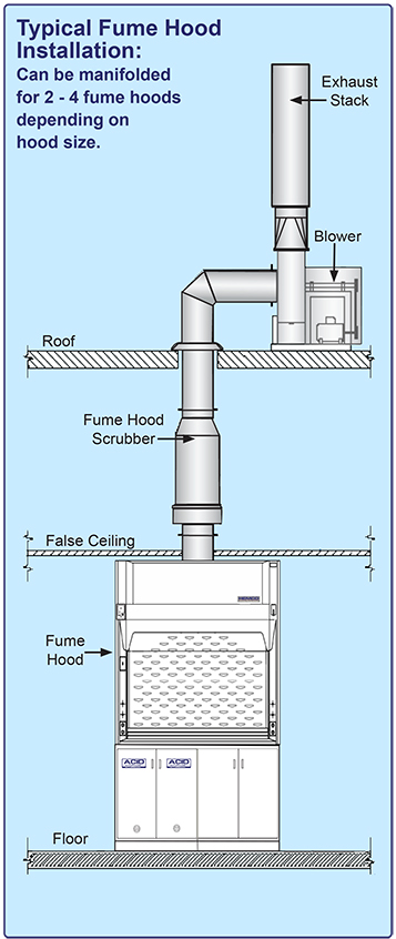
Blower systems must be installed and maintained in order to control the amount of air movement through the hood. Select a blower with a large enough capacity for your application and set-up. Allow for some drop in capacity from fouling by dust and other contaminants.Blowers and ductwork should be arranged so that pressure loss in the system is minimal. Minimize the quantity of elbows and other restrictions. The shortest and straightest arrangements are the most effective and efficient.
It is suggested that each hood have its own blower and ducts for maximum flexibility and to avoid back flow from other hoods. Ductwork systems will also perform efficiently, provided ducts & blowers have been properly sized for the number of hood units in the system. It is recommended that the blowers be located as close as possible to the exhaust end of the duct system. By keeping the number of elbows to a minimum, the air will be under negative pressure; thereby, should a leak occur, clean air would be pulled into the duct rather that contaminated air being pushed out. Where fume hoods are used as part of the laboratory ventilation system, blowers should be in operation at all times. |
|
|
| Regular maintenance of blower and ducting will increase the efficiency of your fume removal system. Blower and ductwork systems should be part of your regular maintenance schedule. Contaminant build-up collected on impeller blades of a centrifugal blower can greatly reduce its capacity. Blowers should be checked to make certain the direction of rotation is correct. Centrifugal blowers will function while rotating in wrong direction but output will be greatly reduced. The above figures show various suggested arrangements of ducts and blowers. Blowers may be installed within the lab, on the roof, on an external wall, or in the fume hood itself. Your choice of arrangements will depend on your particular laboratory location and set-up, facility policies, and building codes. |
|
| Epoxy Coated Steel Blower Belt Drive |
 |
|
 |
Standard (STD) belt drive steel blower and impeller wheel are epoxy coated for superior chemical resistance. Explosion-proof blowers (EXP) have epoxy coated, non-sparking aluminum impeller wheel. V-belt drive and adjustable pulleys permit field balancing. Seven discharge positions to suit installation. Weather housing is furnished. Motor has thermal overload protection. Specify: 115 V single phase, 230 V single phase, 230/460 V three phase or 208 V (consult factory). 1 year manufacturer’s warranty |
| Catalog Number and Static Pressure |
| cfm |
A
Inlet
Diameter |
B
Outlet
Size |
1/2” Static Pressure |
3/4” Static Pressure |
1” Static Pressure |
1 1/2” Static
Pressure |
| HP |
STD |
EXP |
HP |
STD |
EXP |
HP |
STD |
EXP |
HP |
STD |
EXP |
| 296 |
8 7/8” |
10 1/8” x 4 1/8” |
1/4 |
51701 |
51801 |
1/4 |
51702 |
51802 |
1/4 |
51703 |
51803 |
1/4 |
51704 |
51804 |
| 474 |
8 7/8” |
10 1/8” x 4 1/8” |
1/4 |
51705 |
51805 |
1/4 |
51706 |
51806 |
1/4 |
51707 |
51807 |
1/2 |
51708 |
51808 |
| 652 |
8 7/8” |
10 1/8” x 6 3/8” |
1/2 |
51709 |
51809 |
1/2 |
51710 |
51810 |
1/2 |
51711 |
51811 |
1/2 |
51712 |
51812 |
| 800 |
8 7/8” |
10 1/8” x 6 3/8” |
1/2 |
51713 |
51813 |
1/2 |
51714 |
51814 |
1/2 |
51715 |
51815 |
3/4 |
51716 |
51816 |
| 914 |
9 7/8” |
11 1/2” x 8 1/4” |
1/2 |
51717 |
51817 |
3/4 |
51718 |
51818 |
-- |
-- |
-- |
-- |
-- |
-- |
| 1044 |
9 7/8” |
11 1/2” x 8 1/4” |
1/2 |
51719 |
51819 |
1/2 |
51720 |
51820 |
1/2 |
51721 |
51821 |
-- |
-- |
-- |
| 1175 |
9 7/8” |
11 1/2” x 8 1/4” |
1/2 |
51722 |
51822 |
1/2 |
51723 |
51823 |
3/4 |
51724 |
51824 |
-- |
-- |
-- |
| 1240 |
9 7/8” |
11 1/2” x 8 1/4” |
1/2 |
51725 |
51825 |
1/2 |
51726 |
51826 |
3/4 |
51727 |
51827 |
3/4 |
51728 |
51828 |
| 1240 |
11 7/8” |
13 3/8” x 8 1/4” |
1/3 |
51729 |
51829 |
1/2 |
51730 |
51830 |
-- |
-- |
-- |
-- |
-- |
-- |
| 1506 |
11 7/8” |
13 3/8” x 8 1/4” |
3/4 |
51731 |
51831 |
3/4 |
51732 |
51832 |
3/4 |
51733 |
51833 |
-- |
-- |
|
| 1771 |
11 7/8” |
13 3/8” x 8 1/4” |
1 |
51734 |
51834 |
1 |
51735 |
51835 |
1 |
51736 |
51836 |
1 1/2 |
51737 |
51837 |
|
 |
|
| Epoxy Coated Steel Blower Direct Drive |
|
|
 |
Direct drive steel blower and impeller wheel are epoxy coated for superior chemical resistance. Explosion proof blowers have epoxy coated non-sparking aluminum impeller wheels. Motor is 115V, 1 phase and has thermal overload protection. 1 year manufacturer’s warranty |
| Catalog Number and Static Pressure |
A Inlet
Diameter |
B
Outlet Size |
HP |
STD |
EXP |
1/4” SP |
1/2” SP |
3/4” SP |
1” SP |
| cfm |
cfm |
cfm |
cfm |
| 6” |
7” X 4-3/8” |
1/6 |
51177 |
51178 |
565 |
515 |
440 |
300 |
| 8” |
8-3/4” X 5-7/16” |
1/3 |
51179 |
51180 |
935 |
875 |
800 |
712 |
| 9” |
10-1/8” X 4-1/8” |
1/2 |
51181 |
51182 |
1050 |
980 |
920 |
850 |
| 9” |
10-1/8” X 5-1/8” |
3/4 |
51183 |
51184 |
1260 |
1220 |
1180 |
1100 |
|
 |
| Standard motors are 115V, 60Hz / 1 phase. Explosion proof motors are 115/230V, 60Hz, 1 phase. Other voltage, hertz, and phase motors are available. |
|
| Fume Hood Exhaust Blowers Ordering Info |
|
| HEMCO offers a complete line of chemical resistant non-metallic exhaust blowers in belt drive or direct drive options in standard or explosion proof models. Ideal for applications where corrosion resistance is critical. These blowers are available in polypropylene or fiberglass construction. |
|
|
1. It is recommended that exhaust blowers be located at the
end of
the ducting which is typically roof mounted. This ensures a negative pressure through out the ventilation system. However for applications
where the duct is going directly out through a wall above a fume hood,
one option is to have a fiberglass direct drive blower installed in the top of the fume hood. By having the blower internally mounted, the installation is simplified and convenient for duct connection and servicing. However there would be an airflow sound element associated to having the blower hood mounted.
2. By keeping the exhaust duct as short and as straight as
possible,
the total resistance will be reduced and by keeping
the diameter of
the duct correctly sized to the flow volume,
noise and static
pressure can be reduced. |
|
3. Blower wheels for polypropylene and fiberglass blowers are polypropylene.
4. Vibration isolators are recommended when mounting the
blower assemblies
5. HEMCO recommends that a sash stop be installed on the fume hood to limit the sash height for operation. By having
stop at a half open position, the total CFM can be reduced by 50%; thus by reducing the volume, energy loss, duct diameter, motor and blower size, and sound is reduced. |
|
|
| UniFlow SE & LE Fume Hoods |
Hood
Width |
Hood
Depth |
Full
Open cfm |
1/2
Open cfm |
| 36” |
30” |
438 |
241 |
| 48” |
30” |
772 |
385 |
| 60” |
30” |
938 |
474 |
| 72” |
30” |
1162 |
592 |
| 96” |
30” |
1613 |
800 |
| UniFlow CE Fume Hoods |
Hood
Width |
Hood
Depth |
Full
Open cfm |
1/2
Open cfm |
| 30” |
24” |
378 |
189 |
| 36” |
24” |
460 |
230 |
| 48” |
24” |
654 |
327 |
| 72” |
24” |
960 |
480 |
|
• CFM at 100 fpm face velocity
• Housing is constructed of heavy gauged galvanized steel, with a baked enamel
finish, to resist weather & chemical exposures.
• Flange inlet collars enable easy connection to ductwork.
• Wheel is dynamically balanced to minimize noise and increase efficiency.
• Ball bearing pillow blocks are per-lubricated and resistant to both moisture and dirt.
• Shaft is constructed of polished steel with a coating to prevent rust and corrosion.
• Motors meet NEMA standards for single speed motors.
• These blowers are ideally suited for both supply and exhaust applications in laboratories, educational, pharmaceutical, industrial, and other applications. |
|
| Polypropylene Belt Drive Blowers |
|
 |
High efficiency impellers produce low power consumption, reduced operating costs and quiet operation. 20 forward curved blades, in fire retardant polypropylene. Non-static and oil resistant V-belt, cast iron pulleys, adjustable pulleys available, adjustment for tensioning and belt replacement. 230V explosion proof, non sparking, chemical resistant for hostile or hazardous environments. 115V single phase or three phase. Non-static and oil resistant V-belt, cast iron pulleys, adjustable pulleys available, adjustment for tensioning and belt replacement. 1 year manufacturer’s warranty |
 |
| Catalog Number and Static Pressure |
| cfm |
A Inlet
Diameter |
B Outlet
Diameter |
0.5” Static Pressure HP |
0.75” Static Pressure HP |
1.0” Static Pressure HP |
| HP |
STD |
EXP |
HP |
STD |
EXP |
HP |
STD |
EXP |
| 400 |
6” |
6” |
1/4 |
51450 |
51850 |
1/4 |
51460 |
51860 |
1/4 |
51470 |
51870 |
| 800 |
8” |
8” |
1/4 |
51451 |
51851 |
1/3 |
51461 |
51861 |
1/3 |
51471 |
51871 |
| 1000 |
8” |
8” |
1/2 |
51452 |
51852 |
1/2 |
51462 |
51862 |
1/2 |
51472 |
51872 |
| 1200 |
10” |
10” |
1/2 |
51453 |
51853 |
1/2 |
51463 |
51863 |
1/2 |
51473 |
51873 |
| 1600 |
10” |
10” |
1 |
51754 |
51854 |
1 |
51464 |
51864 |
1 |
51474 |
51874 |
|
|
|
|
|
| Ducting and accessories are chemical resistant and easy to install |
|
| Flexible and Rigid PVC Ducting |
4” |
6” |
8” |
10” |
12” |
14” |
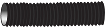 |
1. Flexible Ducting neoprene impregnated fiberglass reinforced with steel helix wire. Standard 12’ lengths. Each piece includes two strap clamps. |
Cat.
No.
80051 |
Cat.
No.
80052 |
Cat.
No.
80053 |
Cat.
No.
80054 |
Cat.
No.
80055 |
Cat.
No.
80056 |
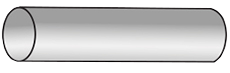 |
2. PVC Rigid Ducting chemical resistant for permanent installations. Standard 10’ lengths with straight ends. |
Cat.
No.
82004 |
Cat.
No.
82006 |
Cat.
No.
82009 |
Cat.
No.
82011 |
Cat.
No.
82013 |
Cat.
No.
82015 |
 |
3. PVC Coupling required to connect straight sections. |
Cat.
No.
82147 |
Cat.
No.
82149 |
Cat.
No.
82153 |
Cat.
No.
82157 |
Cat.
No.
82159 |
Cat.
No.
82160 |
 |
4. PVC 90 degree Elbow used in order to offset obstacles. Has belled ends for duct connections. |
Cat.
No.
82060 |
Cat.
No.
82061 |
Cat.
No.
82063 |
Cat.
No.
82066 |
Cat.
No.
82068 |
Cat.
No.
82069 |
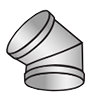 |
5. PVC 45 degree Elbow used in order to offset obstacles. Less static pressure loss than a 90 degree elbow. Has belled ends for duct connections. |
Cat.
No.
82082 |
Cat.
No.
82083 |
Cat.
No.
82085 |
Cat.
No.
82087 |
Cat.
No.
82089 |
Cat.
No.
82090 |
 |
6. PVC 45 degree WYE lateral for joining common ductwork in multiple hood designs. Branch diameter may be sized to 2” to 4” smaller than main diameter. Has belled ends for duct connections. |
Cat.
No.
82216 |
Cat.
No.
82218 |
Cat.
No.
82226 |
Cat.
No.
82229 |
Cat.
No.
82233 |
Cat.
No.
82234 |
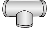 |
7. PVC Tee used in manifold exhaust systems. Has belled ends for duct connection. |
Cat.
No.
82034 |
Cat.
No.
82036 |
Cat.
No.
82038 |
Cat.
No.
82040 |
Cat.
No.
82044 |
Cat.
No.
82046 |
 |
8. PVC Butterfly Damper modifies cfm
for single or multiple hood
arrangement. Has belled ends for duct connection. |
Cat.
No.
82450 |
Cat.
No.
82452 |
Cat.
No.
82454 |
Cat.
No.
82456 |
Cat.
No.
82458 |
Cat.
No.
82460 |
 |
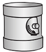
9. PVC Blast Gate Damper a gate that slides in and out to control cfm. Has belled ends for duct connection. |
Cat.
No.
82369 |
Cat.
No.
82371 |
Cat.
No.
82373 |
Cat.
No.
82375 |
Cat.
No.
82377 |
Cat.
No.
82379 |
 |
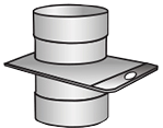
10. PVC Rain Skirt slips over straight pipe on roof to slope water away from cutout. |
Cat.
No.
82328 |
Cat.
No.
82330 |
Cat.
No.
82332 |
Cat.
No.
82334 |
Cat.
No.
82336 |
Cat.
No.
82337 |
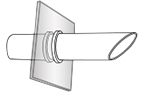 |
11. PVC Vent outlet for horizontal venting through wall or window. Angled end prevents rain from entering.
Male connector included. |
Cat.
No.
80074 |
Cat.
No.
80076 |
Cat.
No.
80077 |
Cat.
No.
80078 |
Cat.
No.
80079 |
Cat.
No.
80080 |
 |
12. Zero Pressure Weather Cap discharges fumes vertically away from roof. Self-draining. Minimal static pressure loss. This is the recommended weather cap. |
Cat.
No.
82350
“A”=16” |
Cat.
No.
82352
“A”=24” |
Cat.
No.
82354
“A”=32" |
Cat.
No.
82356
“A”=40" |
Cat.
No.
82358
“A”=48” |
Cat.
No.
82359
“A”=56” |
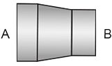 |
13. Round to Round Transition to smaller duct diameter. |
Cat.
No.
82613
4"- 6" |
Cat.
No.
82615
6"- 8" |
Cat.
No.
82617
8"- 10" |
Cat.
No.
82619
10"- 12" |
Cat.
No.
82620
12"- 14" |
Cat.
No.
82621
14"- 16" |
|
|
| Clean Aire HEPA/Carbon In-Line Filtration Systems |
|
|
Clean-Aire HEPA and Carbon Filter Packs are designed to be mounted incline in the exhaust ducting from a fume hood or contaminant source up to 1500 cfm.
The filter pack includes a galvanized steel housing with hinged and gasketed access door for filter change-out and molded composite resin inlet and outlet plenum with duct connection collars sized to meet specification.
Both filters include a 30% pleated prefilter and can be paired together for applications that require particulate and fume removal. |
|
 |
|
| Clean Aire In-Line HEPA Filtration Systems |
|
HEMCO HEPA filter packs effectively collect particulate contaminants from the exhaust air stream. HEPA filters are 99.999% effective
at removing particulate .3 micron and larger. The filter pack housing features a hinged access door with gaskets and spring latches
for convenient filter change. Inlet and outlet plenum's with duct connection collars are installed. The HEPA filter pack can also be paired with a carbon filter pack to remove chemical fumes and odors. |
|
| Note: HEMCO recommends a minihelic or magnehelic gauge to monitor the airflow differential across the filter. The static pressure indicated would alert when to change filter. The gages can be hood or filter mounted. We recommend ordering a back-up replacement filter. |
|
 |
| Clean Aire HEPA Filter Pack |
| CFM |
Size |
Duct Size |
Cat. No. |
| 250-650 |
26” x 15” x 35 1/2” |
4”, 6”,8” diameter |
50188 |
| 650-1200 |
26” x 26” x 35 1/2” |
8”, 10”, 12” diameter |
50189 |
| HEPA Filters |
Prefilter (6 per carton) |
| CFM |
Size |
Cat. No |
CFM |
Size |
Cat. No. |
| 500 |
24” x 12” x 12” |
50094 |
500 |
24” x 12” x 2” |
52000 |
| 1000 |
24” x 24” x 12” |
50095 |
1000 |
24” x 24” x 2” |
52001 |
|
|
| Shown with optional photohelic gauge Cat. No. 51302 |
|
| Filter Housing is fabricated of type-304 stainless steel & requires (1) carbon filter absorber, (1) 24” X 24” X 2” 30% pleated prefilter & (1) bag. |
|
| Bag-In bag-out filters are designed to meet air filtration requirements to handle hazardous fumes and vapors. The housing incorporates a ribbed bagging ring around the side access door over which a specially designed plastic bag is attached. Filters are then installed and changed through the bag to reduce the risk of exposure to personnel. Note: The carbon filter is not included with the housing. We also, recommend the sampling kit below to check if there has been a break through in the carbon filter, and ordering a back-up replacement filter. |
|
 |
| Clean Aire HEPA Filter Bag-In Bag-Out System |
| Description |
CFM |
Size |
Cat. No. |
| Clean-Aire HEPA Filter Bag-In Bag-out System |
1000 |
26” X 26” X 35-1/2” |
51189 |
| HEPA Filters |
1000 |
24” X 24” X 12” |
50195 |
| HEPA Prefilter (6 per carton) |
1000 |
24” X 24” X 2” |
52001 |
| Replacement Bags (2 per carton) |
51989 |
|
|
Minihelic Gauge
Gauge monitors the pressure differential across the HEPA filter, Gauge conveniently mounts on the fume hood or on the filter
housing. Measure range is from 0 to 2.0” wg Gauge is 3” dia. with 5% accuracy Cat. No. 51300 |
|
Magnehelic Gauge
Gauge measures static pressure across the HEPA filter. Mounts on the fume hood or the filter housing. Range of measurement is
from 0 to 2” wg. Gauge is 5” dia with 2% accuracy. Cat. No. 51301 |
|
| Clean Aire In-Line Carbon Filtration Systems |
|
| HEMCO carbon filter packs are used in laboratory exhaust and supply systems to remove chemical odors and vapors from the airstream. Filters are loaded with virgin coconut activated carbon to efficiently absorb organic solvents and acid fumes. The filter pack housing features a hinged access door with gaskets and spring latches for convenient filter changes. Inlet and outlet plenum's with duct connection collars are installed. The carbon filter pack can also be paired with a HEPA filter pak to collect particulate contaminants. |
|
| A standard “01” activated carbon filter for organics is included. HEMCO recommends the sampling kit to check if there has been a breakthrough in the carbon filter, and ordering a back-up replacement filter. |
|
 |
| Clean Aire Carbon Filter Pack |
| CFM |
Size |
Duct Size |
Cat. No. |
| 250-650 |
26” x 15” x 35 1/2” |
4”,8” diameter |
50297 |
| 650-1200 |
26” x 26” x 35 1/2” |
8”, 10”, 12” diameter |
50298 |
| Carbon Filters |
Prefilter (6 per carton) |
| CFM |
Size |
Cat. No |
CFM |
Size |
Cat. No. |
| 500 |
24” x 12” x 12” |
52100 |
500 |
24” x 12” x 2” |
52000 |
| 1000 |
24” x 24” x 12” |
52101 |
1000 |
24” x 24” x 2” |
52001 |
|
|
| Carbon Filter Bag In Bag Out System |
|
| Filter housing is fabricated of type-304 stainless steel & requires (1) carbon filter absorber, (1) 24” X 24” X 2” 30% pleated prefilter & (1) bag. |
|
| Bag-In bag-out filters are designed to meet air filtration requirements to handle hazardous fumes and vapors. The housing incorporates a ribbed bagging ring around the side access door over which a specially designed plastic bag is attached. Old filter is removed then new filters are then installed and changed through the bag to reduce the risk of exposure to personnel. Note: The carbon filter is not included with the housing. We also, recommend the sampling kit below to check if there has been a break through in the carbon filter, and ordering a back-up replacement filter. |
|
|
| Clean Aire Carbon Filter Bag-In Bag-Out System |
| Description |
CFM |
Size |
Cat. No. |
| Clean-Aire Carbon Filter Bag-In Bag-out System |
1000 |
26” X 26” X 35-1/2” |
51198 |
| Carbon Filters |
1000 |
24” X 24” X 12” |
52111 |
| Carbon Prefilter (6 per carton) |
1000 |
24” X 24” X 2” |
50001 |
| Replacement Bags (2 per carton) |
51999 |
|
|
| Clean Aire In-Line Filtration Systems |
|
| The filtration system is rated at 1800 cfm & includes a stainless steel housing with lift off and gasketed access doors for filter change-out and inlet & outlet plenum with duct connection collars sized to meet specification. Bubble tight dampers allow system to close off for filter change. |
|
• Initial filters supplied (excludes prefilters)
• Initial change out bags supplied.
• Inlet/outlet duct connection flanges shall be
a minimum of 1-1/2” wide.
• Approx. shipping weight: 1100 LBS.(without filters)
• Approx. operating weight: 1350 LBS.
• A minimum of four (4) feet of clearance in front of
access door is recommended for filter change-out.
Cat. No. 58998-1 (1) HEPA and Carbon Incline
Cat. No. 58998-2 (2) HEPA and Carbon Online
|
 |
|
|
The following chart is a partial list of contaminants and the proper type of carbon for maximum efficiency. For additional contaminants,
please consult factory. *Filter Check Available |
|
Contaminant |
Type |
Contaminant |
Type |
Contaminant |
Type |
Contaminant |
Type |
Contaminant |
Type |
Acetic Acid |
01 |
Chlorophicbin |
01 |
Ethylene Dichloride |
01 |
Iodine |
01 |
Propyl Mercaptan |
01 |
Acetone |
01 |
Formaldehyde |
01 |
Ethylene Oxide |
06 |
Isopropyl Alcohol |
01 |
Pyridne |
01 |
Ammonia* |
05 |
Cyclohexanone |
01 |
Formaldehyde |
03 |
Isopropyl Ether |
01 |
Styrene Monomer |
01 |
Benzene |
01 |
Dibromoethane |
01 |
Formic Acid* |
02 |
Methyl Butyl Keytone |
01 |
Sulfur Dioxide* |
02 |
Butyl Acetate |
01 |
Dichloronitroethane |
01 |
Formaldehyde |
04 |
Methyl Ethyl Keytone |
01 |
Sulfuric Acid* |
02 |
Caprylic Acid |
01 |
Dichloropropane |
01 |
Heptane |
01 |
Methylene Chloride |
01 |
Toluene |
01 |
Carbolic Acid |
01 |
Dimethyl Sulfate |
01 |
Heptylene |
01 |
Nitric Acid* |
02 |
Trichloroethalene |
01 |
Carbon Tetrachloride |
01 |
Dipropyl Keyton |
01 |
Hexane |
01 |
Nitrobenzene |
01 |
Trichloroethane |
01 |
Chlorine* |
02 |
Ethyl Alcohol |
01 |
Hydrogen Bromide* |
02 |
Nitropropane |
01 |
Xylene |
01 |
Chloroform |
01 |
Ethyl Benzene |
01 |
Hydrogen Chloride* |
02 |
Octalene |
01 |
|
|
|
| Scrubber systems offer high efficiency and minimal maintenance on meeting pollution control requirements. |
|
 |
|
Remote Recirculation Pump
Can be supplied for installations where the scrubber is located outdoors and the possibility of freezing is present. |
| |
| CFM |
Cat. No |
| 500 |
80210 |
| 1000 |
80211 |
| 2000 |
80212 |
| 4000 |
80213 |
| 6000 |
80214 |
| 8000 |
80215 |
|
|
|
 |
PH Control Package
Allows precise control over effluent quality and provides neutralization of contaminants. The PH control system consists of a weather tight, corrosion-proof enclosure containing an analyzer, pre-wired chemical feed pump, weather- protected terminal block, clear PVC face plate and external chemical -feed connection. Enclosure can be mounted on any vertical surface. A heavy-duty industrial probe with a 10” lead wire is supplied, along with (2) 10” lengths of vinyl tubing to connect the feed pump Cat. No. 80112 |
 |
|
|
Fume Scrubbers provide excellent air pollution control for water soluble fumes and odors by moving contaminated air through a filter pack media exposing over forty square feet of surface per cubic foot. Containment is collected on filter media surface and rinsed off with water, excess water is then mechanically removed and cleaned air is released. When conditions require, chemical additives can increase absorptive capacity of the scrubber. Unit includes integral recirculation tank and pump which significantly reduces water consumption and related waste disposal costs. Fan is not included, must be sized to meet exhaust requirements. Request a Plan-A Scrubber specification sheet for planning your scrubber. |
|
| |
Catalog Number and Fume Removal Efficiencies (based on a 3 foot bed) |
Atmospheric Contaminant
|
5 Foot Bed Series |
With pH Control Package |
| Acetic Acid Mist |
NR |
90-95% |
| Alcohols |
* |
* |
| Alkaline Mists, General |
99.9% |
99.9% |
| Aqua Regina Gas |
95-98% |
96-98% |
| Ammonia Gas |
NR |
98-99% |
| Chlorine |
NR |
95-98% |
| Chromic Acid |
99% |
99% |
| Cyanide Solutions |
99.9% |
99.9% |
| Fluoborate Mist |
99% |
99% |
| Formaldehyde |
NR |
98-99% |
| Haldid Mist |
98% |
98% |
| Hydrofloric Acid |
96-99% |
98-99% |
| Hydrogen Cyonide |
NR |
95-98% |
| Nickel Sulfate |
99% |
99% |
| Nitrogen Dioxide |
* |
* |
| Perchloric Acid |
85-90% |
95-98% |
| Phosphoric Acid |
85-90% |
95-98% |
| Sodium Sulfide |
99% |
99% |
| Sulfamate Mist |
99% |
99% |
| Sulfuric Acid |
99.9% |
99.9% |
| Zinc Chloride |
95% |
95% |
|
 |
| Scrubber |
Blower |
| Size |
Dimensions |
Cat.No. |
Size |
Cat.No. |
| A |
B |
C |
| 500 CFM |
49” |
30” |
18” |
80000 |
500 CFM |
80010 |
| 1000 CFM |
50” |
34” |
22” |
80001 |
1000 CFM |
80011 |
| 2000 CFM |
50” |
40” |
28” |
80002 |
2000 CFM |
80012 |
| 3700 CFM |
52” |
49” |
37” |
80003 |
3700 CFM |
80013 |
| 6000 CFM |
53” |
58” |
45” |
80004 |
6000 CFM |
80014 |
| 8000 CFM |
54” |
65” |
52” |
80005 |
8000 CFM |
80015 |
|
| The above efficiencies are intended as a guide representing average values. Specific combinations and concentrations of fumes may result in a significant variation from the above. * Requires extended packing depth and chemical addition to scrubber solution. |
|
|
|
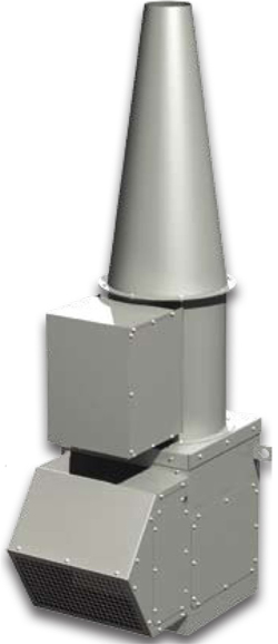
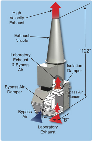
The Fume Hood Scrubber is designed for laboratories that require removal of acid vapors from exhausted air, under the most demanding
corrosive environmental conditions. VS Scrubbers are compact vertical venturi units for indoor installations. |
 |
• Low operating cost
• Sizes from 8” to 20”, larger sizes available
• Highly effective for water soluble acids
• No moving parts to wear out or replace
• Installs directly into exiting duct systems
• Average installation time 2 hours with minimal tools
• Uses no packing material to clog or replace
• Allows the isolation of individual hoods or
..tanks that require pollution reduction
• Low water consumption at a minimum 8 gallons
per hour
• Can be ducted if necessary to meet venting requirements. |
 |
The design of the
In-line fume scrubber
is based on the need
for a simple, compact,
efficient, and water
conservative
apparatus for the
removal of particulates
and water soluble
vapors from individual
laboratory fume hoods. |
 |
| Optimal Air Volume |
240-250 CFM |
580-720 CFM |
890-1000 CFM |
1590-1735 CFM |
1950-2400 CFM |
2400-3052 CFM |
| Overall Height “A” |
38.75” |
44.77” |
50.75” |
61.75” |
73.537” |
78.5” |
| Inlet Diameter “D” |
8” |
10” |
12” |
15” |
18” |
20” |
| |
Cat. No. |
Cat. No. |
Cat. No. |
Cat. No. |
Cat. No. |
Cat. No. |
| PolyPro Construction |
85008 |
85010 |
85012 |
85015 |
85016 |
85018 |
|
|
|
 |
• Installed quickly and easily on reinforced roof curb
• Designed to withstand up to 125 mph wind loads
with out guy wires
• Performance capacities range from 270 - 2400 cfm
and up to 3.5 in. wg per fan
• Meets ANSI Z9.5 , NFPA 45 and ASHRAE guidelines
• U.L. listed for electrical 705 power ventilators
• AMCA Certified for Sound and Air performance
AMCA 210 & 300
• Components are electrostaticaly powder coated with
a 2 part
corrosion resistant coating, standard color:
Gray
• Housing Style is an In-Line Configuration
• 1 Year Warranty
|
 |
|
 |
 |
| Housing Style |
in-line Configuration |
| Stack Style |
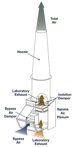
High Plume Nozzle |
| Minimum Flow |
270 cfm |
| Maximum Flow |
24,000 cfm |
| Maximum ESP |
Up to 3.5 in wg (875 Pa) |
| UL Listed |
U.L. for electrical 705 power ventilators |
AMCA
Certified |
Sound and Air performance AMCA210 & 300 |
| Warranty |
1 year |
|
| Unit Size |
Cat. No. |
Dimensions In Inches |
Performance Range (cfm) |
Nozzle Size Range |
| A |
B |
Min |
Max |
Min |
Max |
| 9 |
85009 |
21 5/8 |
21 5/8 |
270 |
1750 |
4 |
9 |
| 10 |
85010 |
21 5/8 |
21 5/8 |
450 |
1800 |
5 |
10 |
| 12 |
85012 |
21 5/8 |
21 5/8 |
600 |
2640 |
6 |
13 |
| 13 |
85013 |
23 5/8 |
23 5/8 |
810 |
3160 |
7 |
14 |
| 16 |
85016 |
27 5/8 |
27 5/8 |
-- |
7080 |
8 |
18 |
|
|
| Proper placement and use of fume hoods and blowers are important laboratory ventilation requirements. HEMCO offers the following suggestions to help in your laboratory layout. |
|
 |
| Supplemental Room Air Supply |
|
| Laboratory supplemental air supply package is designed for situations where there is a shortage in availability of proper air supply to fume hoods. Supplemental air supply package serves as a alternative to auxiliary air hoods by diffusing make-up air to the laboratory rather than creating turbulence at the face of the hood. includes: 2’ x 2’ ceiling diffuser, prefilter, flexible ducting, and fan. |
|
| 500 CFM Package |
1 Diffuser Included |
Cat. No. 90001 |
| 1000 CFM Package |
2 Diffusers Included |
Cat. No. 90002 |
| 1500 CFM Package |
3 Diffusers Included |
Cat. No. 90003 |
|
|
| Laboratory Ventilation Recommendations |
|
| Proper placement and use of fume hoods and blowers are important laboratory ventilation requirements. HEMCO offers the following suggestions to help in your laboratory layout. Please feel free to contact HEMCO’s technical support team in order help with your laboratory needs. |
|
| Typical Ventilation Installations |
 |
|
|

